INFO
More Information About Aorite

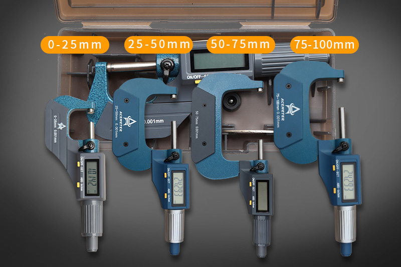
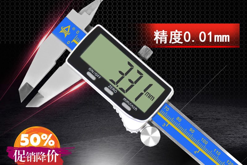
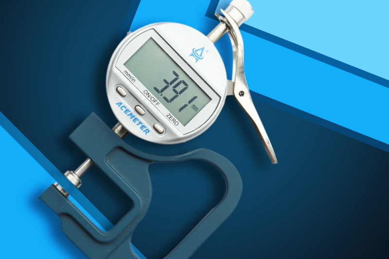
BETTER MEASURING TOOLS ANDBETTER PRODUCTS

(1) The reading of the dial indicator
The measuring rod with the measuring head performs parallel linear motion to the scale disc, and converts the linear motion into a rotary motion and transmits it to the long needle. This long needle will display the movement amount of the measuring rod on the circular dial. One rotation of the long needle is equal to 1mm of the measuring rod, and the long pointer can read 0.01mm. The number of revolution pointer on the dial uses one rotation (1mm) of the long needle as a scale.
A. The pointer of the disc indicator changes with the movement of the measuring axis. Therefore, the measurement only needs to read the scale pointed by the pointer. The picture on the right is an example of the height of the measuring section. To the "0" position, then adjust the probe to the upper section and read the scale indicated by the pointer.
B. A scale is 0.01mm, if the long needle points to 10, the step height difference is 0.1mm
C. If the measuring object is 4mm or 5mm, when the long needle will continuously rotate, it is best to look at the scale pointed by the short needle, and then add the scale pointed by the long pointer.
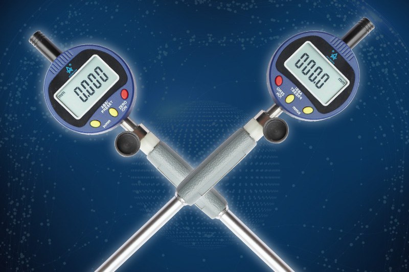
(2) How to use the dial indicator
A. The measuring surface and the measuring rod should be vertical.
B. Use the specified bracket.
C. The probe should lightly touch the measuring object or square gauge.
D. When measuring cylindrical products, the axis of the measuring rod is consistent with the diameter of the product.
(3) Reading and using method of leverage dial indicator
A. The graduation value of the lever dial indicator is 0.01mm, the measuring range is not more than 1mm, and its dial is symmetrically scaled.
B. The measuring surface and probe must be in a horizontal state during use, and under special circumstances, they should also be below 258.
C. Before use, check the spherical probe. If the spherical probe has been ground out of the plane, it should not be used any more.
D. The measuring rod of the lever dial indicator can work in both positive and negative directions. According to the requirements of the measurement direction, the commutator 30 should be moved to the required position.
E. Carrying the measuring rod can make the measuring rod rotate at an angle relative to the shell of the lever dial indicator. According to the measurement needs, the measuring rod should be transported so that the axis of the measuring rod is perpendicular to the direction of the size change of the measured part.
Add:No. 9,Dayuling Road,Dongcheng Street,Dongguan,Guangdong,China
Mob:+86-13602329792 Mr.Zhu
e-mail:1328583449@qq.com

Scan QR code